University Physics
Electromagnetic Lab

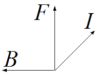
Figure 1 Current flowing in a loop of wire interacts with the
B field
to produce a force, F. The net force on the wire is upward. An equal but opposite
downward force is exerted on the magnet.
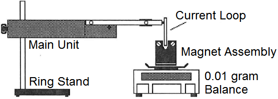
Figure 2 Forces generated by currents flowing in the magnetic field
are measured by the 0.01 gram balance scale.
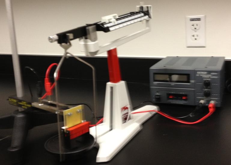
Figure 3 The experimental setup is shown.
A quadruple-beam balance measures the weight of the magnet assembly.
A power supply provides current to the wire in the magnetic field.
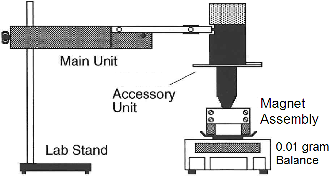
Figure 4 The apparatus shown allows the direction of the current
relative to the magnetic field to be varied.
|
Lab 5 Magnetic Forces
In this lab, we investigate magnetic forces on a current carrying wire.
Magnetic fields exert forces on charges, but the charge must be moving as they are in currents.
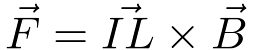
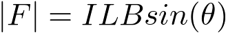
The force exerted on a current carrying wire by a magnetic field is,
| (1) |
where I is the current, L is the length of the wire, and B is the magnetic field in Teslas.
This assumes the wire is straight and the magnetic field is uniform.
 Recall the cross product. The force vector in equation 1, is perpendicular to
both the current and the magnetic field,
and is in the direction a right hand screw will advance when the current vector is turned into the
magnetic field vector.
Recall the cross product. The force vector in equation 1, is perpendicular to
both the current and the magnetic field,
and is in the direction a right hand screw will advance when the current vector is turned into the
magnetic field vector.
For the current and magnetic field shown in Figure 1, the force on the wire will be up.
An equal but opposite force is exerted on the magnet. The force on the magnet will be down.
The magnet rests on the scale. The force exerted
on the magnet effects the weight of the magnet seen by the scale. The setup is shown in Figure 2.
The magnitude of the force on a current carrying wire in a magnetic field is,
| (2) |
Since the current is perpendicular to the magnetic field, the magnitude of the force is,

| (3) |
where I is the current, L
is the length of the wire segment, and B is the magnetic field.
In the course of performing this experiment, we shall reinforce
- proper use of electrical meters,
- notions of direct and indirect measurement,
- use of a quadruple-beam balance to measure force,
- use of experiment to corroborate or falsify theory, and
- error analysis.
Force versus Current
- Set up the equipment as shown in Figures 2 and 3.
The current coil should not touch the magnet. Place an ammeter in
series with the power supply to measure the current.
-
Weigh the magnet holder with no current flowing. Record this value.
-
Set the current to 0.5 amp. Record the new scale reading.
-
Continue, increasing the current in 0.5 amp increments to a maximum of 5.0 amp.
-
Subtract the weight of the magnet holder to determine the force produced by the
current. Convert the weight in grams to the force in Newtons.
Plot the force (Newtons) as a function of current.
Force as a function of the Length of Wire
- Determine the length of the conductive foil, L .
-
Weigh the magnet holder with no current flowing. Record this value.
-
Set the current to 2.0 amps. Record the scale reading.
-
Subtract the mass with no current from the mass measured with current flowing. Convert the mass
(grams) to force (Newtons).
-
Turn off the current. Remove the Current Loop and replace it with another.
- Measure the force produced by the new Current Loop.
- Plot a graph of the force as a function of the length of the wire.
Force versus Angle
-
Set up the apparatus as shown in Figure 4.
-
With no current flowing, determine the mass of the Magnet Assembly.
Set the angle to zero, with the axis of the coil perpendicular to the magnetic field (Current parallel to the magnetic field). Set the current to one amp.
Record the new "mass". Determine the force in Newtons on the coil. Record this value. It should be zero.
-
Increase the angle in 5o increments. to 90o, and then in -5o increments to - 90o . At each angle, record the force.
-
Plot a graph of the Force vs the angle.
Reflect upon your observations.
Q: What is the value of the B field?
Q: How do measured force values compare with the formula,
?