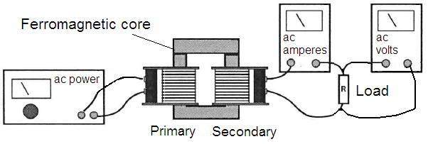
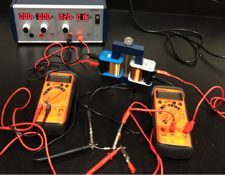
University Physics
Electromagnetics Lab


Figure 1  


Figure 2  


Figure 3  

Lab 6     Faraday's Law

In this lab, we investigate the generation of a voltage by a time varying magnetic field. Faraday's law states that the voltage generated in a loop is equal to the time derivative of the magnetic flux passing through the loop.
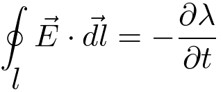
(1)
where the magnetic flux,
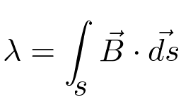
l is the perimeter of the surface s. The surface s is the cross-sectional area of the ferromagnetic core. The flux flows around the core. It flows through the coils, generating voltages in them when it changes in response to the alternating current.

Equipment

  1. Four coils, 200 Turns, 400 Turns, 400 Turns, and 800 Turns

  2. U-shaped ferromagnetic core

  3. Low voltage AC power supply 0-6 VAC, 0-1 amp

  4. An AC ammeter 0-2 A (Don't exceed 2A or you will blow the fuse in the ammeter)

  5. An AC voltmeter

  6. Three 2 watt resistors: 10, 100, and 1000 Ohms

  7. Banana connecting leads
Procedure

  1. Set up the coils, core and 100 Ohm load resistor as shown in Figures 1 and 2. The coil on the left connected to the AC supply is the primary coil. The coil on the right connected to the load is the secondary coil. In general power flows from the primary to the secondary coil. The structure in Figure 1 is a transformer. Transformers can either step up or step down the AC voltage level.

  2. With the 400-turn coil as the primary and the 400-turn coil as the secondary, adjust the input voltage to 6.0 volts AC. With a load resistance of 1000 Ohms connected to the secondary, measure the input current, the output voltage and the output current.

  3. Repeat step 2 replacing the 1000 Ohm load with a 100 Ohm load resistor.

  4. Repeat step 2 replacing the 100 Ohm load with a 10 Ohm load resistor.

  5. Repeat steps 2 -4 using different combinations of primary and secondary coils.

  6. Replace the secondary coil with a relatively large diameter wire (18-20 gauge) wound around the core 5-6 times as shown in Figure 3. Set the primary voltage to 6.0 VAC. Connect an ammeter to the new secondary. Measure the current with the only resistance being that of the ammeter. Disconnect the ammeter and measure the secondary voltage.

    STEP
    FIVE
    [Reflect]

    Reflect upon your observations.

    Q: Is the ratio of the secondary voltage to the primary voltage the same as the turns ratio, as predicted by ideal transformer theory? What might cause it to differ?