Np = 1000
Ns = 100
Figure 2
Figure 2a
Figure 3
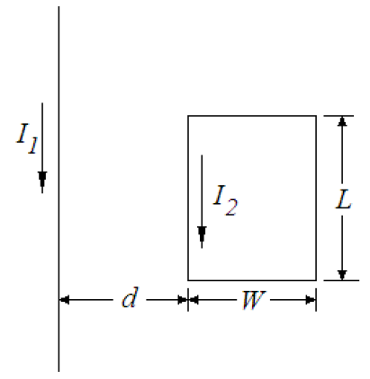
Figure 4
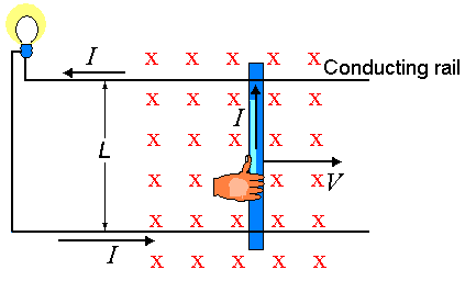
Figure 5 The induced emf causes an
induced current I to appear in the circuit.
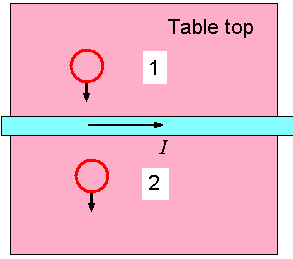
Figure 6
Np = 1000 Ns = 100
|
How long is each rod?
Determine the direction of the induced current, clockwise or counterclockwise, as the loop moves pastJustify your answers.
- position 1 and
- position 2.
Determine the angle between the transmission axis of the polarizer and the analyzer.
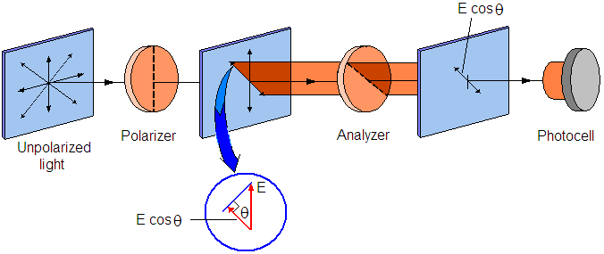 Figure 7 |