Schematic Capture
Schematic capture software creates PSPICE input files
from circuit drawings. This reduces common errors.
Errors in the input file are troublesome because PSPICE will
not run, but many times, especially for large circuits, enough
errors are eliminated so PSPICE runs, but errors remain causing
a faulty simulation.
Using this software we will draw a circuit and simulate it with PSPICE.
This software is FREE and available on-line.
It runs on your PC.
To start the program, left click START > MicroSimEVAL7.1> Schematics
The following window comes up. Using the DRAW pulldown menu,
select Get New Part..., as shown


The part browser window shown on the right comes up. Here we
choose an npn transistor. Click on Place. The transistor then
appears in the schematic window. Double click to position the
transistor. Select resistors, ground and a dc voltage supply for VCC.
To rotate a component, select it and type control_r.
To move a component, select and drag.
Connect components using the WIRE command. Pull down the DRAW menu and choose
Wire. Left click to start a wire and make turns. Double click to
terminate a wire.
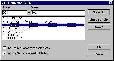
To change values, select the component by clicking on it.
Use the EDIT pulldown menu and choose attributes. The following window comes up.
Here we are changing the power supply to 10V. Select DC = and type 10V in the
Value box in the attribute window shown below.

Also, place the component IPROBE in wires to measure current and
the component VIEWPOINT at nodes to measure voltages.
IPROBEs appear as meters in the schematic below.
The meters shown are in backwards. They will register negative currents.
To rotate, select and type control_r.
VIEWPOINTS appear as triangles pointing to nodes in the schematic.
We have also labeled nodes by double clicking on them. A window
comes up where we can enter the node label. We have labeled
node 1, the collector, base and emitter nodes.

Save the schematic. The Title Box info (not shown) can be changed by selecting
it and using the EDIT pulldown menu to change attributes.
Now create a netlist (PSPICE input file) using the Analysis pulldown
menu and selecting Create Net List.
Here we then looked at the netlist using the Examine Netlist in the
Analysis pulldown menu. The following window came up.

The schematic looks reasonable so lets try simulating it.
Select Simulate in the Analysis pulldown menu. The following
window resulted.

The voltages and currents appear on the schematic window as shown below.
and also on the usual
PSPICE output file.
The PSPICE output file references the file
lab1ckt2.net


