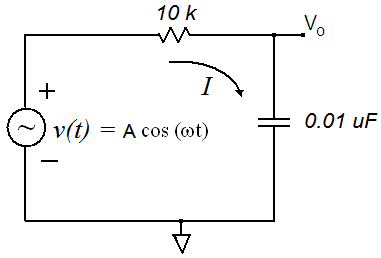
Figure 1 RC Circuit

|
Figure 1 RC Circuit
|
Lab 7 Exercise
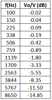
The input and output voltages for the circuit shown in Figure 1 were measured and the gain, Vo/V was calculated in dB. Recall that,
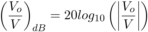
(1)
Plot the gain in dB as a function frequency on the attached semilog paper. Use the logarithmic axis for the frequency.
Q. What is the value of the RC time constant?